Need Help? Contact Us Trade Customer? Register / Login
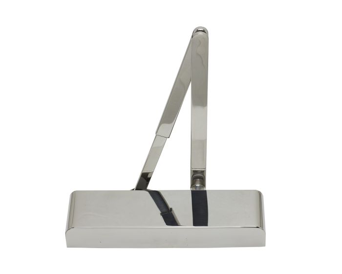
Slimline Overhead Door Closer With Backcheck - CE / UKCA Marked - Fire Rated - Certifire Approved - EN1154 Power Size 2-5 - Adjustable Via Spring - 240mm x 69mm x 49mm - Polished Stainless Steel
Catalogue Number:
49027
- Polished stainless steel overhead door closer
- Features individual controls for door speed, latching action and backcheck.
- Can be adjusted to suit door widths up 1250mm wide.
- EN power size - 2-5.
- Max Door Width / Weight – 1250mm / 100Kg.
- Adjustable closing speed.
- Adjustable latch speed.
- Power adjustable by spring.
- Adjustable backcheck.
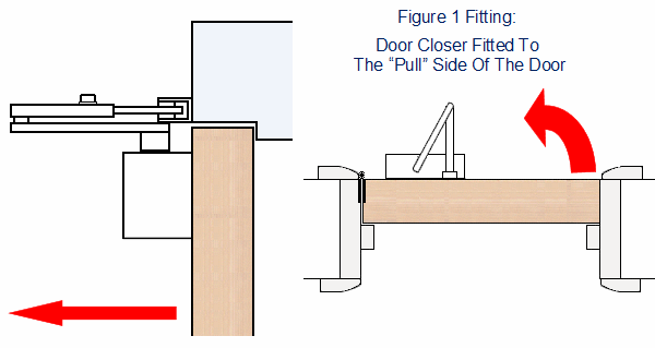
- Universal application (Fig 1, 6 & 61) - Suitable for all opening applications including "pull-open", "push-open" & "transom mounting".
- CE marked against EN1154 in fig 1 and fig 6 positions only..
- Included in successful fire test to EN1634.
- Certifire approved.
- Declaration of performance (DoP) available
Finish
- Polished stainless steel
- Supplied with slimline semi-radius silve cover and matching Polished stainless steel arms.
Fixing Positions & Mounting Options:
- Out of the box this door closer can be fitted in three fixing positions, including the push side of the door (figure 1), pull side of the door (figure 6) and transom mounted (figure 61).
- Figure 1 - pull side mounting - (covered under the CE mark - suitable for use on fire doors).
- Closer fitted to the pull side of the door
- Body fitted to the door with arms fitted to the door frame.
- In this position the closer arms will project out from the door into the room.
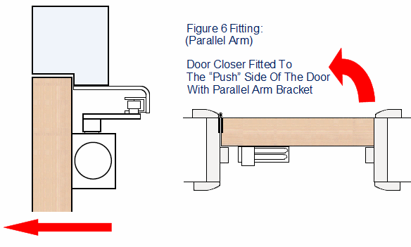
- Figure 6 - push side mounting - (covered under the CE mark - suitable for use on fire doors).
- Closer fitted to the push side of the door.
- Body fitted to the door with arms fitted to the door frame via a parallel arm bracket (supplied with each unit).
- In this position the closer arms will lie flat against the door running parallel with the door frame.
- Sometime known as figure 66.
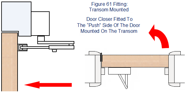
- Figure 61 - Transom mounted to the push side of the door - Please note this option is not covered under the CE mark and should not be used on fire doors).
- Closer fitted to the transom on the push side of the door.
- Body fitted to the transom (door frame) with the arms fitted to the door.
- In this position the closer arms will project out from the door into the room.
Power Adjustment Via Spring:
- Separate power adjustment, by means of an allen key at the end of the closer body, this closer can be adjusted to suit door widths from 850mm to 1250mm EN power size 2-5
| EN Power Size Setting | Maximum Door Width (mm) | Maximum Door Weight (kg) |
|---|---|---|
| 2 | 850mm | 40kg |
| 3 | 950mm | 60kg |
| 4 | 1100mm | 80kg |
| 5 | 1250mm | 100kg |
Adjustable Closing Speed:
- The closing speed can be adjusted by turning a small screw in the body of the closer.
- By turning the screw in the body the rate at which oil flows through the closer changes in turn controlling how fast the closer will shut the door.
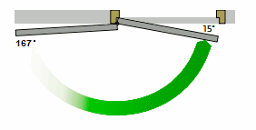
- Speed adjustment can be controlled from approximately the first 180 degrees down to the last 15 degrees of the closing cycle.
Adjustable Latch Action:
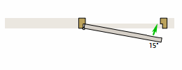
- The last 15 degrees of the closing cycle is known as the latch action (or snap action), it's designed to help give a door closer a little extra force to help it overcome any door seals, or latches that might prevent the door from closing within the frame.
- The latch action can be adjusted by turning a screw in the body of the closer.
- By turning the latch action off or very low the door closer will softly close into the frame, by turning the latch action to it's maximum setting the door closer will push into the door frame with extra force.
Adjustable Backcheck:
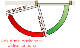
- This function slows and or stops the door during it's opening cycle, so that it cannot be flung open violently and damage any adjacent walls.
- Backcheck function can be adjusted by turning a small screw in the body of the closer.
Closer Dimensions:
- Body Length - 236mm
- Body Height - 55mm
- Body Depth - 38mm
- Cover Length - 240mm
- Cover Height - 69mm
- Cover Depth - 49mm
Opening Forces - BS 8300:
The opening force (0-30 degrees) is less than 30N when fitted to a minimum door width of 900mm when fitted in figure 1 fixing position and to a minimum door width of 826mm when fitted in figure 6 fixing position.
The opening force (30-60 degrees) is less the 22.5N when fitted to a minimum door width of 826mm.
Therefor, to meet the requirements of BS 8300 the minimum door width when fitted in figure 1 position is 900mm. When fitted in figure 6 position the minimum door width is 826mm
| Item | 49027 |
|---|---|
| Item Code | 49027 |
| Finish | Polished Stainless Steel |
| Dimensions | 240mm x 75mm x 49mm |
| Fire Rated | FD30 / FD60 - Fire Rated |
| Sold Per | Each |
| Availability | Stock item - please allow 1-3 days for delivery |
Stock item - please allow 1-3 days for delivery

